|
|
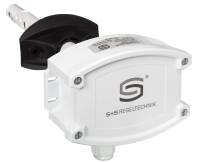
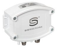
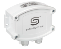
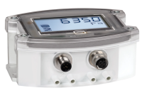
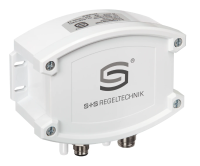
RHEASREG® KLGFVT-Modbus (LCD)Calibratable duct air flow sensor RHEASGARD® KLGFVT - Modbus with Modbus connector, housing made of impact-resistant plastic with quick-locking screws, with cable gland (optional M12-connector as per DIN EN 61076-2-101) optionally with/ without display, to determine the flow velocity (0.1...20 m/s) and temperature (0...+50 °C). The following parameters can be retrieved from the Modbus: flow velocity, volume flow (calculated) and temperature. The flow sensors are suitable for monitoring or controlling airflows in ducts, at fans and dampers, for flow-dependent monitoring of humidifiers and electric heating registers according to DIN 57100, Sect. 420, or for use in connection with DDC systems. Innovative Modbus sensor with galvanically separated RS485 Modbus interface, selectable bus termination resistance, DIP switch for setting the bus parameters and bus address in current-free state, internal LEDs for telegram status display, two separate push-in terminals and large three-line display (illuminated; with customised programming in the 7-segment and dot-matrix range). The sensor is factory-calibrated.

Collect
Voltage supply 24 V AC/ DC (± 10 %) Measuring range Volume flow 0...200.000 m3/h Start bridging 0...120 s (can be set via Modbus) Measuring range, temperature 0...+50 °C Measuring accuracy 0.5 m/s + 3 % measured value Warm up time < 2 min Response time < 60 s Reproducibility ± 1.0 % final value Current consumption approx. 4 VA Measuring range 0,1...20 m/s Ambient temperature storage –20...+ 50 °C operation 0...+ 50 °C Medium pollutant-free, non-precipitating air Process connection by mounting flange (included in the scope of delivery) Sensor Calorimetric, temperature compensated, sensor breakage protection, with manual zero-point calibration (via button) Electrical connection 0.2 - 1.5 mm2, via push-in terminal Housing dimensions 126 x 90 x 50 mm (Tyr 2) Cable gland M 16 x 1.5, including strain relief, exchangeable, max. inner diameter 10.4 mm Long-term stability ± 0.5 % final value per year Max. sensor cable length 50 m, avoid laying parallel with mains voltage-carrying lines, or use shielded cables, minimum cross section 1.5 mm2 per conductor, apply cable screen one-sided Humidity < 98% r.H. pollutant-free, non-precipitating air Protective tube PLEUROFORMTM, material polyamide (PA6), with torsion protection, Ø 20mm, NL = 221 mm, vmax = 30 m/s (air), stainless steel V2A (1.4301), Ø 16 mm available upon request as an option Protection class III (according to EN 60 730) Protection type IP 65 (according to EN 60 529)* Cable connection cable gland, plastic (M 16 x 1.5; with strain relief, exchangeable, max. inner diameter 10.4 mm) or M12 connector according to DIN EN 61076-2-101 (optional on request) Housing plastic, UV-stabilised, material polyamide, 30 % glass-globe reinforced, with quick-locking screws (slotted/ Phillips head - combination), colour traffic white (similar to RAL 9016), housing cover for display is transparent ! Standards CE conformity, according to EMC directive 2014/ 30/ EU, according to EN 61326-1, according to EN 61326-2-3 Optional Display with illumination, three-line, cutout approx. 70 x 40 mm (W x H), to display the flow velocity, volume flow and temperature (cyclical) or a selectable parameter (static) |